บริษัท RAKwireless ได้ออกผลิตภัณท์ใหม่ในชื่อ Link.ONE ออกแบบมาเพื่อให้เป็นบอร์ดพัฒนาอุปกรณ์ IoT ด้วยโปรแกรม Arduino IDE แบบ all-in-one รองรับการเชื่อมต่อ LTE-M, NB-IoT และ LoRaWAN อยู่ในอุปกรณ์เดียวกัน ครอบคลุมเทคโนโลยีการสื่อสารไร้สายระยะไกลที่ใช้พลังงานต่ำ (LPWAN : Low Power Wide Area Network) โดยมีวัตถุประสงค์ เพื่อให้เราสามารถเลือกใช้ช่องทางหลักในการสื่อสารไร้สาย และกำหนดช่องทางสื่อสารไร้สายสำรองเอาไว้ให้พร้อม เมื่อใดที่ช่องทางสื่อสารหลักใช้งานไม่ได้ เราก็สามารถเปลี่ยนไปใช้ช่องทางสำรองแทนได้ เป็นผลทำให้อุปกรณ์ IoT จะยังคงสามารถรับ-ส่งข้อมูลได้อยู่ตลอดเวลา
Features
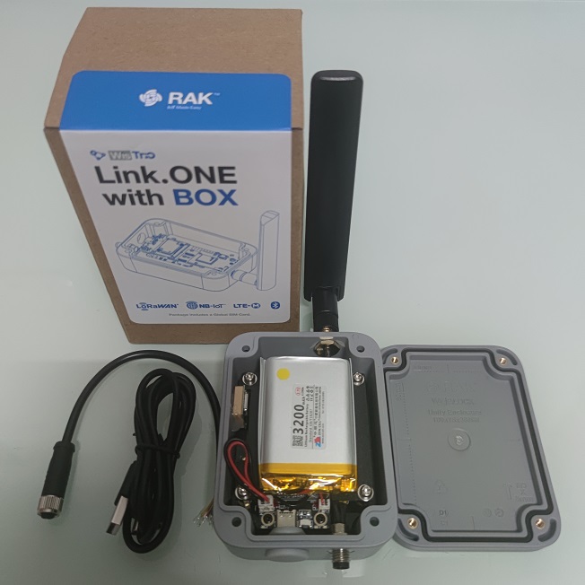
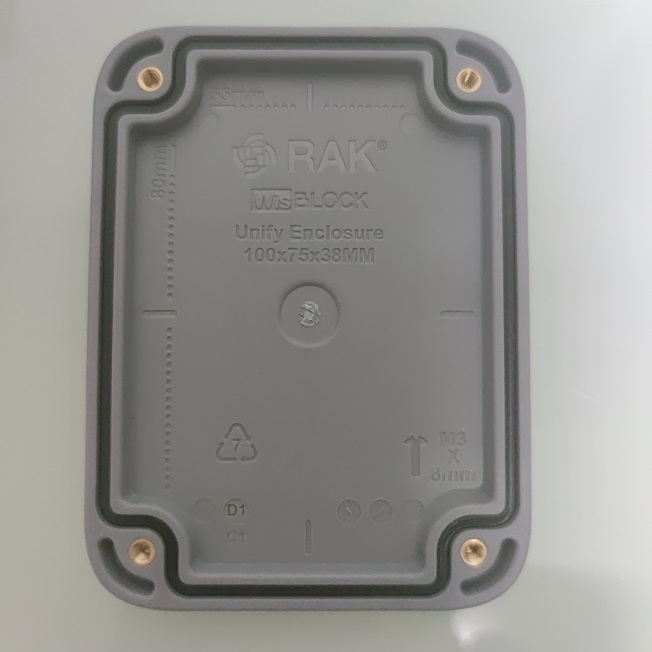
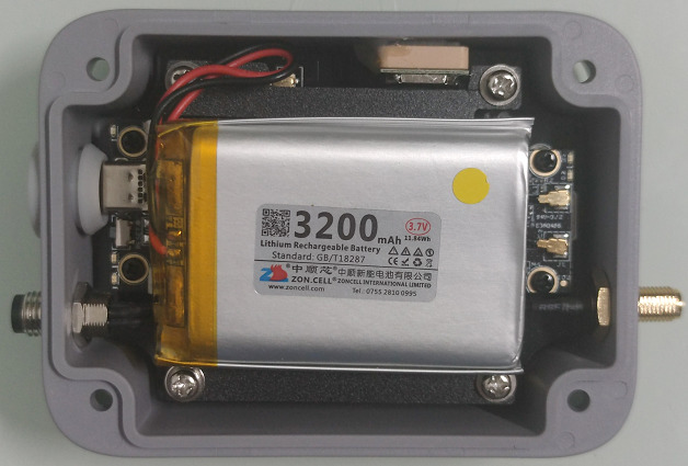
Link.ONE เป็นการนำเอาบอร์ด มาใส่ในกล่อง WisBlock Unify Enclosure ขนาด 100 x 75 x 38 mm. พร้อมลิเธียมแบตเตอร์แบบชาร์จได้ 3.7 Volts ความจุ 3200 mAh. เมื่อพัฒนาใช้งานในแบบ Sleep mode และรับ-ส่งข้อมูลไม่ถี่มากเกินไป ก็จะทำให้มีพลังงานไฟฟ้าเพียงพอ โดยไม่ต้องจัดหาแหล่งจ่ายไฟจากภายนอก
Unboxing
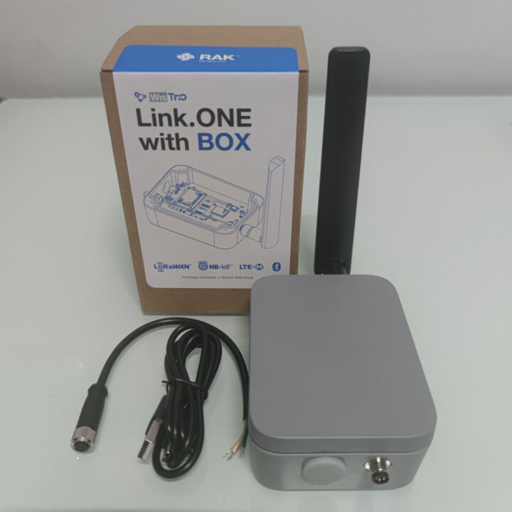
อุปกรณ์ถูกจัดเรียงอย่างแน่นมาก ภายในกล่องจะประกอบด้วยอุปกรณ์ดังต่อไปนี้
- 1 x WisTrio LTE-M NB-IoT LoRaWAN Development Board
- 1 x ลิเธียมแบตเตอร์แบบชาร์จได้
- 1 x เสาอากาศภายนอกสำหรับ Cellular
- 1 x USB Type-C cable
- 1 x Circular Female M8 connector cable
ตัวกล่องแข็งแรง ฝากล่องจะมียางกันน้ำอยู่ในร่อง IP65 enclosure เวลาปิดฝาจะทำให้แนบสนิทกันมาก
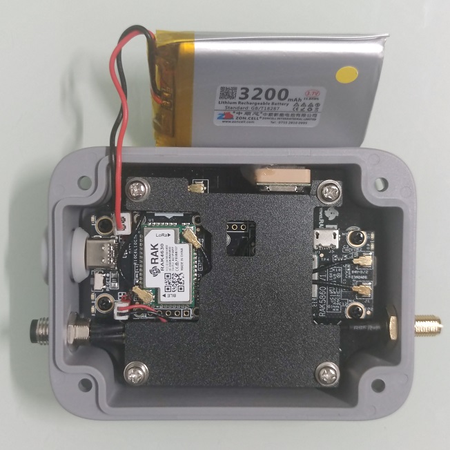
เมื่อถอดแบตเตอรี่ออก ก็จะเห็นบอร์ด WisTrio LTE-M NB-IoT LoRaWAN Development Board
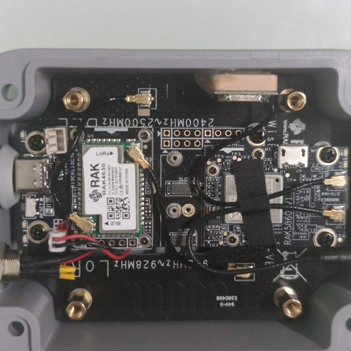
Modules Inside
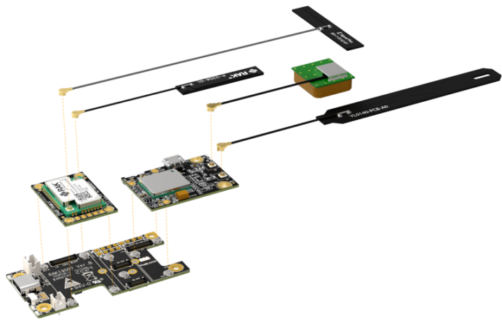
- Module RAK4631 : nRF52840 (MCU + BLE) และ Semtech SX1262 (LoRA/LoRaWAN)
- Module RAK5860 : Quectel BG77 (NB-IoT + LTE-M) with GPS
- Module RAK19007 : USB Type-C และ Li-ion Charger
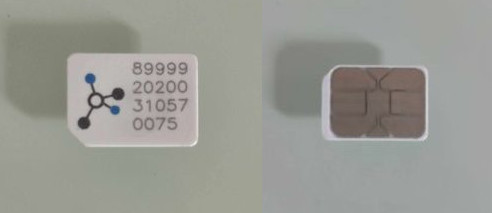
- Monogoto SIM Card : Data package ในระบบ Cellular ขนาด 500 MB. สามารถใช้งานได้นานถึง 10 ปี
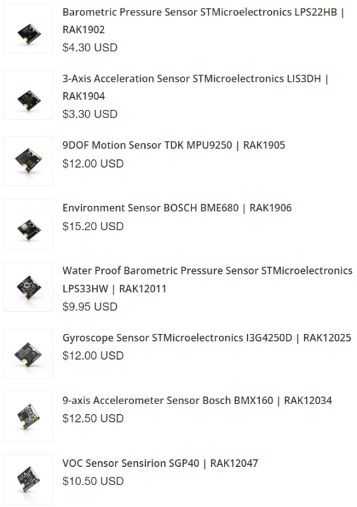
- นอกจากนี้ เรายังสามารถซื้อ Sensor Module มาต่อเพิ่มกับ Link.ONE เพื่อวัดค่าต่างๆ ได้อีกด้วย
LPWAN (Low Power Wide Area Network)
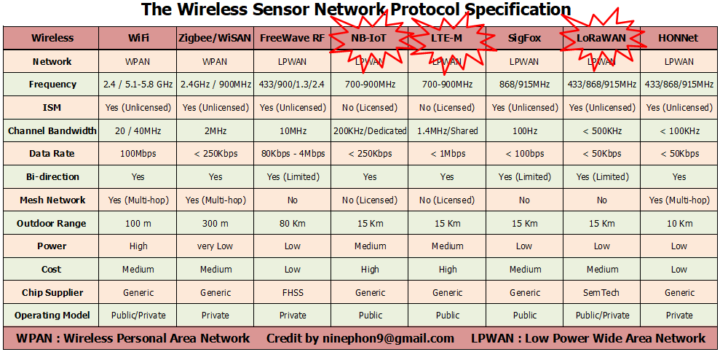
Link.ONE รองรับเทคโนโลยีการสื่อสารไร้สายระยะไกลแบบใช้พลังงานต่ำ ประกอบด้วย LTE-M, NB-IoT และ LoRaWAN
- NB-IoT : Narrow Band Internet of Things เป็นเทคโนโลยีที่มีการพัฒนาต่อยอดมาจากระบบ LTE (4G) เพื่อให้อุปกรณ์สามารถเชื่อมต่อกันแบบไร้สาย โดยผ่านโครงข่ายของสัญญาณโทรศัพท์เคลื่อนที่ เหมาะกับการทำงานร่วมกับแอปพลิคชันที่ไม่ต้องการความเร็วในการส่งข้อมูลมากนัก เช่น Smart Parking หรือ Smart Metering
- LTE-M : Long Term Evolution of Machines เป็นเทคโนโลยีที่เหมือนกับ NB-IoT ที่ให้อุปกรณ์สามารถเชื่อมต่อกันผ่านโครงข่ายสัญญาณโทรศัพท์เคลื่อนที่ แต่จะแตกต่างกันที่ความเร็วในการส่งข้อมูลสูงกว่า NB-IoT แต่ยังคงประหยัดพลังงาน เหมาะกับแอปพลิเคชันติดตามตำแหน่งอุปกรณ์ เช่น Smart Transportaion และ Asset Tracking
- LoRaWAN : Long Range Wide Area Network เป็นเทคโนโลยีสัญญาณวิทยุที่อาศัยโปรโตคอล LoRa ที่ออกแบบมาเพื่อรองรับการเชื่อมต่ออุปกรณ์แบบใช้พลังงานต่ำ และสื่อสารข้อมูลในระยะไกลข้ามเน็ตเวิร์ค รองรับทั้งแบบ Private และ Public เช่น การเชื่อมต่ออุปกรณ์อัจฉริยะต่างๆ
หมายเหตุ 1. ผู้รีวิวไม่ได้ทดสอบการเชื่อมต่อแบบ NB-IoT เนื่องจากต้องเสียค่าใช้จ่ายในการลงทะเบียนครั้งแรกเพื่อเปิด Monogoto SIM Card และค่าใช้จ่ายรายปีสำหรับ Network Server on Cloud จาก Operator ที่ให้บริการในประเทศไทย
หมายเหตุ 2. ผู้รีวิวไม่ได้ทดสอบการเชื่อมต่อแบบ LTE-M เนื่องจาก Monogoto SIM Card ที่ให้มากับผลิตภัณฑ์ Link.ONE ไม่รองรับ Operator ที่ให้บริการในประเทศไทย
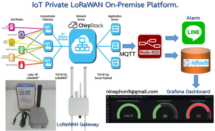
IoT Private LoRaWAN On-Premise Platform
เป็น IoT Platform ที่ผู้รีวิวติดตั้งขึ้นมาใช้งานเป็นการส่วนตัว เพื่อความสะดวกในการบริหารจัดการระบบ LoRaWAN ได้อย่างเบ็ดเสร็จ ประกอบด้วยซอฟท์แวร์ต่างๆ ที่จำเป็นในการใช้งาน ซึ่งอยู่ในรูปแบบของ Open Source ทั้งหมดและไม่มีค่าใช้จ่ายดังนี้
- ChirpStack : LoRaWAN Network and Application Server ทำการลงทะเบียนหมายเลขอุปกรณ์ LoRaWAN IoT และถอดรหัสข้อมูลที่ได้รับในรูปแบบ AES128 และมีตัวกลาง MQTT broker (Message Queuing Telemetry Transport) โดยทำหน้าที่เป็นผู้ส่ง (publish)
- Node-RED : เป็นเครื่องมือพัฒนาแบบโฟลว์สำหรับการเขียนโปรแกรม โดยเป็นผู้รับ (subscribe) มาจาก ChirpStack ผ่านโปรโตคอล MQTT และนำข้อมูลจาก payload มาถอดรหัสตามรูปแบบ BASE64 ก็จะได้ข้อมูลที่ส่งมาจากเซนเซอร์ นำไปเก็บไว้ที่ InfluxDB และตรวจสอบกำหนดค่าแจ้งเตือนไปที่ LINE Notify Application
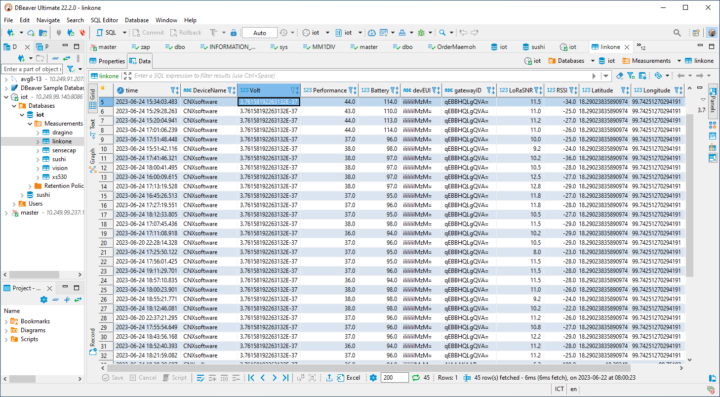
- InfluxDB : Time Series Database ใช้เก็บข้อมูลที่มาจากเซนเซอร์และข้อมูลที่มาจาก LoRaWAN Gateway ไว้ในฐานข้อมูล โดยเรียงตามอนุกรมของเวลาโดยอัตโนมัติ ทำให้เราสามารถนำข้อมูลไปวิเคราะห์ หรือดูย้อนหลังได้ตลอดเวลา
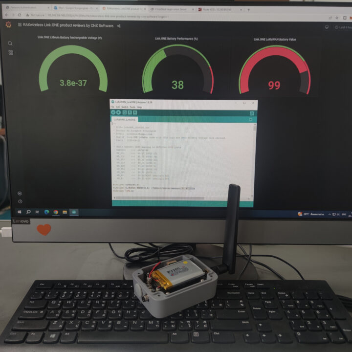
- Grafana : Real Time Dashboard นำข้อมูลจากฐานข้อมูลมาแสดงผลในรูปแบบต่างๆ
- Line Notify : เมื่อเซนเซอร์มีค่าสูงหรือต่ำกว่าที่กำหนดไว้ LINE Application จะแจ้งเตือนให้เราทราบผ่านทางระบบ LINE Notify เพียงครั้งเดียว แต่หาก Sensor มีค่าเปลี่ยนแปลงไปจากค่าตอนแรก ก็จะกลับมาแจ้งเตือนอีกครั้งหนึ่ง นั่นหมายความว่า จะไม่มีการแจ้งเตือนกรณีที่มีค่าซ้ำๆ เดิมเกิดขึ้นนั่นเอง
Preliminary Preparation
- Materials required
1 x Link.ONE
1 x USB Type-C cable
1 x LoRaWAN Gateway
1 x Computer - Software Install
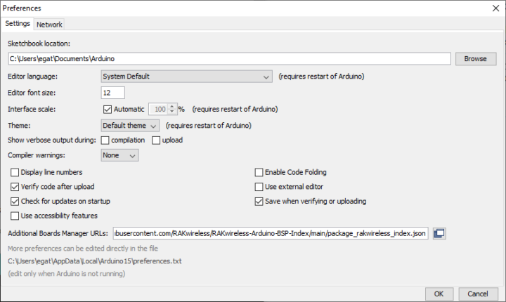
Step 1. Arduino IDE Install https://www.arduino.cc/en/softwareStep 2. เพิ่มอุปกรณ์ Link.ONE : Arduino menu File -> Preferences คัดลอก url https://raw.githubusercontent.com/RAKwireless/RAKwireless-Arduino-BSP-Index/main/package_rakwireless_index.json ไปวางไว้ที่ช่อง Additional Boards Manager URLs:
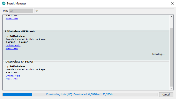
- Click on Tools -> Board -> Board Manager -> ค้นหาคำว่า “RAKwireless nRF Boards” -> กดปุ่ม Install บอร์ด WisBlock RAK4631
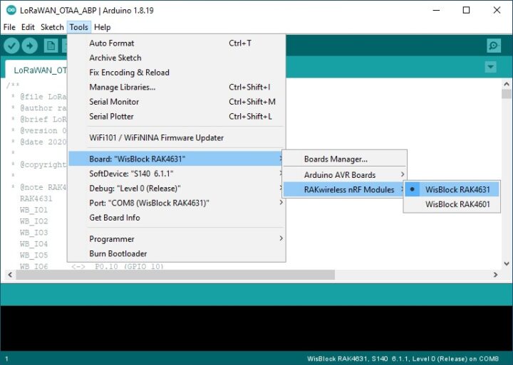
- Click on Tools -> Board -> Board Manager -> RAKwireless nRF Boards -> กดเลือกบอร์ด WisBlock RAK4631
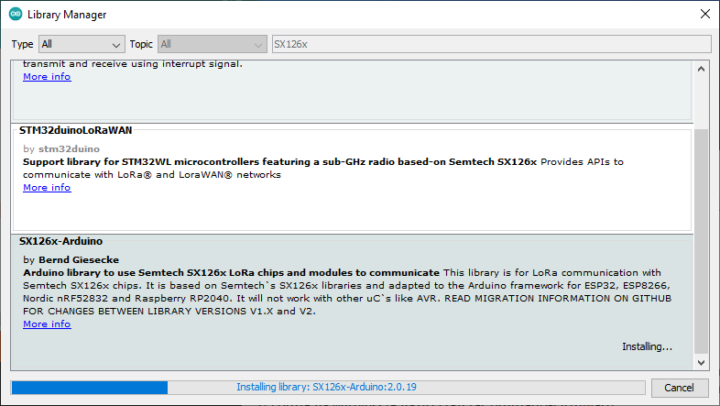
Step 3. เพิ่ม Library Source Code : Arduio menu Sketch -> Include Library -> Library Manager ค้นหาคำว่า “SX126x-Arduino” -> กดปุ่ม Install
LoRaWAN Test run
1. Hello “NinePhon” : เขียนโปรแกรมlส่งข้อความให้ Link.ONE เชื่อมต่อในแบบ LoRaWAN
กำหนดย่านความถี่ใช้งานสำหรับประเทศไทยคือ AS923
กำหนดการเชื่อมต่อเป็นแบบ OTAA ประกอบด้วยค่าต่างๆ ดังนี้
DevEUI = 88 88 88 88 88 88 33 33
AppKey = 88 88 88 88 88 88 88 88 88 88 88 88 88 88 88 88
AppEUI = B8 27 EB FF FE 39 00 00
หมายเหตุ : กระบวนการ Activation มี 2 แบบคือ ABP (Activation By Personalization) และ OTAA (Over The Air Activation)
|
1 2 3 4 5 6 7 8 9 10 11 12 13 14 15 16 17 18 19 20 21 22 23 24 25 26 27 28 29 30 31 32 33 34 35 36 37 38 39 40 41 42 43 44 45 46 47 48 49 50 51 52 53 54 55 56 57 58 59 60 61 62 63 64 65 66 67 68 69 70 71 72 73 74 75 76 77 78 79 80 81 82 83 84 85 86 87 88 89 90 91 92 93 94 95 96 97 98 99 100 101 102 103 104 105 106 107 108 109 110 111 112 113 114 115 116 117 118 119 120 121 122 123 124 125 126 127 128 129 130 131 132 133 134 135 136 137 138 139 140 141 142 143 144 145 146 147 148 149 150 151 152 153 154 155 156 157 158 159 160 161 162 163 164 165 166 167 168 169 170 171 172 173 174 175 176 177 178 179 180 181 182 183 184 185 186 187 188 189 190 191 192 193 194 195 196 197 198 199 200 201 202 203 204 205 206 207 208 209 210 211 212 213 214 215 216 217 218 219 220 221 222 223 224 225 226 227 228 229 230 231 232 233 234 235 236 237 238 239 240 241 242 243 244 245 246 247 248 249 250 251 252 253 254 255 256 257 258 259 260 261 262 263 264 265 266 267 268 269 270 271 272 273 274 275 276 277 278 279 280 281 282 283 284 285 286 287 288 289 290 291 292 293 294 295 296 297 298 299 300 301 302 |
/** * @file LoRaWAN_OTAA_ABP.ino * @author rakwireless.com * @brief LoRaWan node example with OTAA/ABP registration * @version 0.1 * @date 2020-08-21 * * @copyright Copyright (c) 2020 * * @note RAK4631 GPIO mapping to nRF52840 GPIO ports RAK4631 <-> nRF52840 WB_IO1 <-> P0.17 (GPIO 17) WB_IO2 <-> P1.02 (GPIO 34) WB_IO3 <-> P0.21 (GPIO 21) WB_IO4 <-> P0.04 (GPIO 4) WB_IO5 <-> P0.09 (GPIO 9) WB_IO6 <-> P0.10 (GPIO 10) WB_SW1 <-> P0.01 (GPIO 1) WB_A0 <-> P0.04/AIN2 (AnalogIn A2) WB_A1 <-> P0.31/AIN7 (AnalogIn A7) */ #include <Arduino.h> #include <LoRaWan-RAK4630.h> //http://librarymanager/All#SX126x #include <SPI.h> // RAK4630 supply two LED #ifndef LED_BUILTIN #define LED_BUILTIN 35 #endif #ifndef LED_BUILTIN2 #define LED_BUILTIN2 36 #endif bool doOTAA = true; // OTAA is used by default. #define SCHED_MAX_EVENT_DATA_SIZE APP_TIMER_SCHED_EVENT_DATA_SIZE /**< Maximum size of scheduler events. */ #define SCHED_QUEUE_SIZE 60 /**< Maximum number of events in the scheduler queue. */ #define LORAWAN_DATERATE DR_0 /*LoRaMac datarates definition, from DR_0 to DR_5*/ #define LORAWAN_TX_POWER TX_POWER_5 /*LoRaMac tx power definition, from TX_POWER_0 to TX_POWER_15*/ #define JOINREQ_NBTRIALS 3 /**< Number of trials for the join request. */ DeviceClass_t g_CurrentClass = CLASS_A; /* class definition*/ LoRaMacRegion_t g_CurrentRegion = LORAMAC_REGION_AS923; /* Region: AS923 */ lmh_confirm g_CurrentConfirm = LMH_UNCONFIRMED_MSG; /* confirm/unconfirm packet definition*/ uint8_t gAppPort = LORAWAN_APP_PORT; /* data port*/ /**@brief Structure containing LoRaWan parameters, needed for lmh_init() */ static lmh_param_t g_lora_param_init = {LORAWAN_ADR_ON, LORAWAN_DATERATE, LORAWAN_PUBLIC_NETWORK, JOINREQ_NBTRIALS, LORAWAN_TX_POWER, LORAWAN_DUTYCYCLE_OFF}; // Foward declaration static void lorawan_has_joined_handler(void); static void lorawan_join_failed_handler(void); static void lorawan_rx_handler(lmh_app_data_t *app_data); static void lorawan_confirm_class_handler(DeviceClass_t Class); static void send_lora_frame(void); /**@brief Structure containing LoRaWan callback functions, needed for lmh_init() */ static lmh_callback_t g_lora_callbacks = {BoardGetBatteryLevel, BoardGetUniqueId, BoardGetRandomSeed, lorawan_rx_handler, lorawan_has_joined_handler, lorawan_confirm_class_handler, lorawan_join_failed_handler }; //OTAA keys !!!! KEYS ARE MSB !!!! uint8_t nodeDeviceEUI[8] = {0x88, 0x88, 0x88, 0x88, 0x88, 0x88, 0x33, 0x33}; uint8_t nodeAppEUI[8] = {0xB8, 0x27, 0xEB, 0xFF, 0xFE, 0x39, 0x00, 0x00}; uint8_t nodeAppKey[16] = {0x88, 0x88, 0x88, 0x88, 0x88, 0x88, 0x88, 0x88, 0x88, 0x88, 0x88, 0x88, 0x88, 0x88, 0x88, 0x88}; // ABP keys uint32_t nodeDevAddr = 0x260116F8; uint8_t nodeNwsKey[16] = {0x7E, 0xAC, 0xE2, 0x55, 0xB8, 0xA5, 0xE2, 0x69, 0x91, 0x51, 0x96, 0x06, 0x47, 0x56, 0x9D, 0x23}; uint8_t nodeAppsKey[16] = {0xFB, 0xAC, 0xB6, 0x47, 0xF3, 0x58, 0x45, 0xC7, 0x50, 0x7D, 0xBF, 0x16, 0x8B, 0xA8, 0xC1, 0x7C}; // Private defination #define LORAWAN_APP_DATA_BUFF_SIZE 64 /**< buffer size of the data to be transmitted. */ #define LORAWAN_APP_INTERVAL 20000 /**< Defines for user timer, the application data transmission interval. 20s, value in [ms]. */ static uint8_t m_lora_app_data_buffer[LORAWAN_APP_DATA_BUFF_SIZE]; //< Lora user application data buffer. static lmh_app_data_t m_lora_app_data = {m_lora_app_data_buffer, 0, 0, 0, 0}; //< Lora user application data structure. TimerEvent_t appTimer; static uint32_t timers_init(void); static uint32_t count = 0; static uint32_t count_fail = 0; void setup() { pinMode(LED_BUILTIN, OUTPUT); digitalWrite(LED_BUILTIN, LOW); // Initialize Serial for debug output time_t timeout = millis(); Serial.begin(115200); while (!Serial) { if ((millis() - timeout) < 5000) { delay(100); } else { break; } } // Initialize LoRa chip. lora_rak4630_init(); Serial.println("====================================="); Serial.println("Welcome to RAK4630 LoRaWan!!!"); if (doOTAA) { Serial.println("Type: OTAA"); } else { Serial.println("Type: ABP"); } switch (g_CurrentRegion) { case LORAMAC_REGION_AS923: Serial.println("Region: AS923"); break; case LORAMAC_REGION_AU915: Serial.println("Region: AU915"); break; case LORAMAC_REGION_CN470: Serial.println("Region: CN470"); break; case LORAMAC_REGION_CN779: Serial.println("Region: CN779"); break; case LORAMAC_REGION_EU433: Serial.println("Region: EU433"); break; case LORAMAC_REGION_IN865: Serial.println("Region: IN865"); break; case LORAMAC_REGION_EU868: Serial.println("Region: EU868"); break; case LORAMAC_REGION_KR920: Serial.println("Region: KR920"); break; case LORAMAC_REGION_US915: Serial.println("Region: US915"); break; case LORAMAC_REGION_RU864: Serial.println("Region: RU864"); break; case LORAMAC_REGION_AS923_2: Serial.println("Region: AS923-2"); break; case LORAMAC_REGION_AS923_3: Serial.println("Region: AS923-3"); break; case LORAMAC_REGION_AS923_4: Serial.println("Region: AS923-4"); break; } Serial.println("====================================="); //creat a user timer to send data to server period uint32_t err_code; err_code = timers_init(); if (err_code != 0) { Serial.printf("timers_init failed - %d\n", err_code); return; } // Setup the EUIs and Keys if (doOTAA) { lmh_setDevEui(nodeDeviceEUI); lmh_setAppEui(nodeAppEUI); lmh_setAppKey(nodeAppKey); } else { lmh_setNwkSKey(nodeNwsKey); lmh_setAppSKey(nodeAppsKey); lmh_setDevAddr(nodeDevAddr); } // Initialize LoRaWan err_code = lmh_init(&g_lora_callbacks, g_lora_param_init, doOTAA, g_CurrentClass, g_CurrentRegion); if (err_code != 0) { Serial.printf("lmh_init failed - %d\n", err_code); return; } // Start Join procedure lmh_join(); } void loop() { // Put your application tasks here, like reading of sensors, // Controlling actuators and/or other functions. } /**@brief LoRa function for handling HasJoined event. */ void lorawan_has_joined_handler(void) { if(doOTAA == true) { Serial.println("OTAA Mode, Network Joined!"); } else { Serial.println("ABP Mode"); } lmh_error_status ret = lmh_class_request(g_CurrentClass); if (ret == LMH_SUCCESS) { delay(1000); TimerSetValue(&appTimer, LORAWAN_APP_INTERVAL); TimerStart(&appTimer); } } /**@brief LoRa function for handling OTAA join failed */ static void lorawan_join_failed_handler(void) { Serial.println("OTAA join failed!"); Serial.println("Check your EUI's and Keys's!"); Serial.println("Check if a Gateway is in range!"); } /**@brief Function for handling LoRaWan received data from Gateway * * @param[in] app_data Pointer to rx data */ void lorawan_rx_handler(lmh_app_data_t *app_data) { Serial.printf("LoRa Packet received on port %d, size:%d, rssi:%d, snr:%d, data:%s\n", app_data->port, app_data->buffsize, app_data->rssi, app_data->snr, app_data->buffer); } void lorawan_confirm_class_handler(DeviceClass_t Class) { Serial.printf("switch to class %c done\n", "ABC"[Class]); // Informs the server that switch has occurred ASAP m_lora_app_data.buffsize = 0; m_lora_app_data.port = gAppPort; lmh_send(&m_lora_app_data, g_CurrentConfirm); } void send_lora_frame(void) { if (lmh_join_status_get() != LMH_SET) { //Not joined, try again later return; } uint32_t i = 0; memset(m_lora_app_data.buffer, 0, LORAWAN_APP_DATA_BUFF_SIZE); m_lora_app_data.port = gAppPort; m_lora_app_data.buffer[i++] = 'N'; m_lora_app_data.buffer[i++] = 'i'; m_lora_app_data.buffer[i++] = 'n'; m_lora_app_data.buffer[i++] = 'e'; m_lora_app_data.buffer[i++] = 'P'; m_lora_app_data.buffer[i++] = 'h'; m_lora_app_data.buffer[i++] = 'o'; m_lora_app_data.buffer[i++] = 'n'; m_lora_app_data.buffsize = i; lmh_error_status error = lmh_send(&m_lora_app_data, g_CurrentConfirm); if (error == LMH_SUCCESS) { count++; Serial.printf("lmh_send ok count %d\n", count); } else { count_fail++; Serial.printf("lmh_send fail count %d\n", count_fail); } } /**@brief Function for handling user timerout event. */ void tx_lora_periodic_handler(void) { TimerSetValue(&appTimer, LORAWAN_APP_INTERVAL); TimerStart(&appTimer); Serial.println("Sending frame now..."); send_lora_frame(); } /**@brief Function for the Timer initialization. * * @details Initializes the timer module. This creates and starts application timers. */ uint32_t timers_init(void) { TimerInit(&appTimer, tx_lora_periodic_handler); return 0; } |
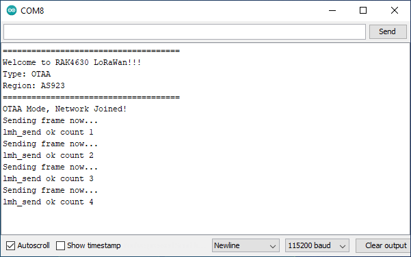
Arduino IDE หลังจาก Compiler Source code และ Upload ลงบอร์ด Link.ONE เราสามารถ Flash program ได้ทันที โดยไม่ต้องกดปุ่มใดๆ และบอร์ดจะทำงานตามที่ได้โปรแกรมไว้โดยอัตโนมัติ นี่ถือเป็นข้อดีของ Link.ONE สำหรับนักพัฒนาโปรแกรม
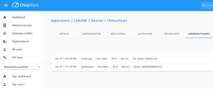
- Join Request : เริ่มต้น Link.ONE จะทำการร้องขอการเชื่อมต่อกับ LoRaWAN Network Server ผ่านทาง LoRaWAN Gateway
- Join Accept : LoRaWAN Network Server จะทำการตรวจสอบหมายเลข DeviceEUI ของ Link.ONE หากได้ลงทะเบียนไว้แล้ว ก็จะตอบรับคำขอให้สามารถรับ-ส่งข้อมูลกันได้ต่อไป
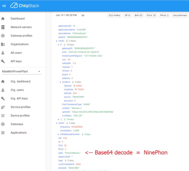
จากรูป data payload คือ “TmluZVBob24=” เมื่อนำมาถอดรหัสตามมาตรฐาน Base64 Decode ก็จะได้คำว่า “NinePhon” นั่นเอง
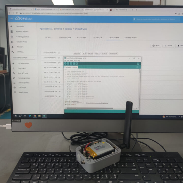
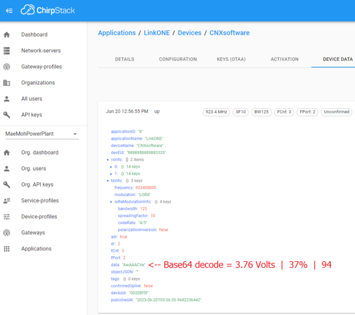
2. เนื่องจากบริษัท RAKwireless ไม่ได้ส่งตัวอย่าง Sensor board มาให้ ทางผู้รีวิวจึงเขียนโปรแกรมให้อ่านค่า Voltage/Performance/LoRaWAN Value จากแบตเตอรี่ลิเธียมไอออน เพื่อเป็นตัวแทนของเซ็นเซอร์สำหรับการรีวิวในครั้งนี้
|
1 2 3 4 5 6 7 8 9 10 11 12 13 14 15 16 17 18 19 20 21 22 23 24 25 26 27 28 29 30 31 32 33 34 35 36 37 38 39 40 41 42 43 44 45 46 47 48 49 50 51 52 53 54 55 56 57 58 59 60 61 62 63 64 65 66 67 68 69 70 71 72 73 74 75 76 77 78 79 80 81 82 83 84 85 86 87 88 89 90 91 92 93 94 95 96 97 98 99 100 101 102 103 104 105 106 107 108 109 110 111 112 113 114 115 116 117 118 119 120 121 122 123 124 125 126 127 128 129 130 131 132 133 134 135 136 137 138 139 140 141 142 143 144 145 146 147 148 149 150 151 152 153 154 155 156 157 158 159 160 161 162 163 164 165 166 167 168 169 170 171 172 173 174 175 176 177 178 179 180 181 182 183 184 185 186 187 188 189 190 191 192 193 194 195 196 197 198 199 200 201 202 203 204 205 206 207 208 209 210 211 212 213 214 215 216 217 218 219 220 221 222 223 224 225 226 227 228 229 230 231 232 233 234 235 236 237 238 239 240 241 242 243 244 245 246 247 248 249 250 251 252 253 254 255 256 257 258 259 260 261 262 263 264 265 266 267 268 269 270 271 272 273 274 275 276 277 278 279 280 281 282 283 284 285 286 287 288 289 290 291 292 293 294 295 296 297 298 299 300 301 302 303 304 305 306 307 308 309 310 311 312 313 314 315 316 317 318 319 320 321 322 323 324 325 326 327 328 329 330 331 332 333 334 335 336 337 338 339 340 341 342 343 344 345 346 347 348 349 350 351 352 353 354 355 356 |
/** * @file LoRaWAN_LinkONE.ino * @author Mr.Suraphon Kongangkab * @eMail [email protected] * @brief Link.ONE LoRaWan node with OTAA join and send Battery Voltage data payload. * @date 2023-06-20 * * @note RAK4631 GPIO mapping to nRF52840 GPIO ports RAK4631 <-> nRF52840 WB_IO1 <-> P0.17 (GPIO 17) WB_IO2 <-> P1.02 (GPIO 34) WB_IO3 <-> P0.21 (GPIO 21) WB_IO4 <-> P0.04 (GPIO 4) WB_IO5 <-> P0.09 (GPIO 9) WB_IO6 <-> P0.10 (GPIO 10) WB_SW1 <-> P0.01 (GPIO 1) WB_A0 <-> P0.04/AIN2 (AnalogIn A2) WB_A1 <-> P0.31/AIN7 (AnalogIn A7) */ #include <Arduino.h> #include <LoRaWan-RAK4630.h> //http://librarymanager/All#SX126x #include <SPI.h> // RAK4630 supply two LED #ifndef LED_BUILTIN #define LED_BUILTIN 35 #endif #ifndef LED_BUILTIN2 #define LED_BUILTIN2 36 #endif bool doOTAA = true; // OTAA is used by default. #define SCHED_MAX_EVENT_DATA_SIZE APP_TIMER_SCHED_EVENT_DATA_SIZE /**< Maximum size of scheduler events. */ #define SCHED_QUEUE_SIZE 60 /**< Maximum number of events in the scheduler queue. */ #define LORAWAN_DATERATE DR_0 /*LoRaMac datarates definition, from DR_0 to DR_5*/ #define LORAWAN_TX_POWER TX_POWER_5 /*LoRaMac tx power definition, from TX_POWER_0 to TX_POWER_15*/ #define JOINREQ_NBTRIALS 3 /**< Number of trials for the join request. */ DeviceClass_t g_CurrentClass = CLASS_A; /* class definition*/ LoRaMacRegion_t g_CurrentRegion = LORAMAC_REGION_AS923; /* Region: AS923 */ lmh_confirm g_CurrentConfirm = LMH_UNCONFIRMED_MSG; /* confirm/unconfirm packet definition*/ uint8_t gAppPort = LORAWAN_APP_PORT; /* data port*/ /**@brief Structure containing LoRaWan parameters, needed for lmh_init() */ static lmh_param_t g_lora_param_init = {LORAWAN_ADR_ON, LORAWAN_DATERATE, LORAWAN_PUBLIC_NETWORK, JOINREQ_NBTRIALS, LORAWAN_TX_POWER, LORAWAN_DUTYCYCLE_OFF}; // Foward declaration static void lorawan_has_joined_handler(void); static void lorawan_join_failed_handler(void); static void lorawan_rx_handler(lmh_app_data_t *app_data); static void lorawan_confirm_class_handler(DeviceClass_t Class); static void send_lora_frame(void); /**@brief Structure containing LoRaWan callback functions, needed for lmh_init() */ static lmh_callback_t g_lora_callbacks = {BoardGetBatteryLevel, BoardGetUniqueId, BoardGetRandomSeed, lorawan_rx_handler, lorawan_has_joined_handler, lorawan_confirm_class_handler, lorawan_join_failed_handler }; //OTAA keys !!!! KEYS ARE MSB !!!! uint8_t nodeDeviceEUI[8] = {0x88, 0x88, 0x88, 0x88, 0x88, 0x88, 0x33, 0x33}; uint8_t nodeAppEUI[8] = {0xB8, 0x27, 0xEB, 0xFF, 0xFE, 0x39, 0x00, 0x00}; uint8_t nodeAppKey[16] = {0x88, 0x88, 0x88, 0x88, 0x88, 0x88, 0x88, 0x88, 0x88, 0x88, 0x88, 0x88, 0x88, 0x88, 0x88, 0x88}; // ABP keys uint32_t nodeDevAddr = 0x260116F8; uint8_t nodeNwsKey[16] = {0x7E, 0xAC, 0xE2, 0x55, 0xB8, 0xA5, 0xE2, 0x69, 0x91, 0x51, 0x96, 0x06, 0x47, 0x56, 0x9D, 0x23}; uint8_t nodeAppsKey[16] = {0xFB, 0xAC, 0xB6, 0x47, 0xF3, 0x58, 0x45, 0xC7, 0x50, 0x7D, 0xBF, 0x16, 0x8B, 0xA8, 0xC1, 0x7C}; // Private defination #define LORAWAN_APP_DATA_BUFF_SIZE 64 /**< buffer size of the data to be transmitted. */ #define LORAWAN_APP_INTERVAL 60000 /**< Defines for user timer, the application data transmission interval. 60s, value in [ms]. */ static uint8_t m_lora_app_data_buffer[LORAWAN_APP_DATA_BUFF_SIZE]; //< Lora user application data buffer. static lmh_app_data_t m_lora_app_data = {m_lora_app_data_buffer, 0, 0, 0, 0}; //< Lora user application data structure. TimerEvent_t appTimer; static uint32_t timers_init(void); static uint32_t count = 0; static uint32_t count_fail = 0; // Read Battery #define PIN_VBAT WB_A0 uint32_t vbat_pin = PIN_VBAT; #define VBAT_MV_PER_LSB (0.73242188F) // 3.0V ADC range and 12 - bit ADC resolution = 3000mV / 4096 #define VBAT_DIVIDER_COMP (1.73) // Compensation factor for the VBAT divider, depend on the board #define REAL_VBAT_MV_PER_LSB (VBAT_DIVIDER_COMP * VBAT_MV_PER_LSB) float readVBAT(void) { float raw; // Get the raw 12-bit, 0..3000mV ADC value raw = analogRead(vbat_pin); return raw * REAL_VBAT_MV_PER_LSB; } uint8_t mvToPercent(float mvolts) { if (mvolts < 3300) return 0; if (mvolts < 3600) { mvolts -= 3300; return mvolts / 30; } mvolts -= 3600; return 10 + (mvolts * 0.15F); // thats mvolts /6.66666666 } uint8_t mvToLoRaWanBattVal(float mvolts) { if (mvolts < 3300) return 0; if (mvolts < 3600) { mvolts -= 3300; return mvolts / 30 * 2.55; } mvolts -= 3600; return (10 + (mvolts * 0.15F)) * 2.55; } void setup() { pinMode(LED_BUILTIN, OUTPUT); digitalWrite(LED_BUILTIN, LOW); // Initialize Serial for debug output time_t timeout = millis(); Serial.begin(115200); while (!Serial) { if ((millis() - timeout) < 5000) { delay(100); } else { break; } } // Initialize LoRa chip. lora_rak4630_init(); Serial.println("====================================="); Serial.println("Welcome to RAK4630 LoRaWan!!!"); if (doOTAA) { Serial.println("Type: OTAA"); } else { Serial.println("Type: ABP"); } switch (g_CurrentRegion) { case LORAMAC_REGION_AS923: Serial.println("Region: AS923"); break; case LORAMAC_REGION_AU915: Serial.println("Region: AU915"); break; case LORAMAC_REGION_CN470: Serial.println("Region: CN470"); break; case LORAMAC_REGION_CN779: Serial.println("Region: CN779"); break; case LORAMAC_REGION_EU433: Serial.println("Region: EU433"); break; case LORAMAC_REGION_IN865: Serial.println("Region: IN865"); break; case LORAMAC_REGION_EU868: Serial.println("Region: EU868"); break; case LORAMAC_REGION_KR920: Serial.println("Region: KR920"); break; case LORAMAC_REGION_US915: Serial.println("Region: US915"); break; case LORAMAC_REGION_RU864: Serial.println("Region: RU864"); break; case LORAMAC_REGION_AS923_2: Serial.println("Region: AS923-2"); break; case LORAMAC_REGION_AS923_3: Serial.println("Region: AS923-3"); break; case LORAMAC_REGION_AS923_4: Serial.println("Region: AS923-4"); break; } Serial.println("====================================="); //creat a user timer to send data to server period uint32_t err_code; err_code = timers_init(); if (err_code != 0) { Serial.printf("timers_init failed - %d\n", err_code); return; } // Setup the EUIs and Keys if (doOTAA) { lmh_setDevEui(nodeDeviceEUI); lmh_setAppEui(nodeAppEUI); lmh_setAppKey(nodeAppKey); } else { lmh_setNwkSKey(nodeNwsKey); lmh_setAppSKey(nodeAppsKey); lmh_setDevAddr(nodeDevAddr); } // Initialize LoRaWan err_code = lmh_init(&g_lora_callbacks, g_lora_param_init, doOTAA, g_CurrentClass, g_CurrentRegion); if (err_code != 0) { Serial.printf("lmh_init failed - %d\n", err_code); return; } // Start Join procedure lmh_join(); // Read Battery // Set the analog reference to 3.0V (default = 3.6V) analogReference(AR_INTERNAL_3_0); // Set the resolution to 12-bit (0..4095) analogReadResolution(12); // Can be 8, 10, 12 or 14 // Let the ADC settle delay(1); // Get a single ADC sample and throw it away readVBAT(); } void loop() { // Put your application tasks here, like reading of sensors, // Controlling actuators and/or other functions. } /**@brief LoRa function for handling HasJoined event. */ void lorawan_has_joined_handler(void) { if(doOTAA == true) { Serial.println("OTAA Mode, Network Joined!"); } else { Serial.println("ABP Mode"); } lmh_error_status ret = lmh_class_request(g_CurrentClass); if (ret == LMH_SUCCESS) { delay(1000); TimerSetValue(&appTimer, LORAWAN_APP_INTERVAL); TimerStart(&appTimer); } } /**@brief LoRa function for handling OTAA join failed */ static void lorawan_join_failed_handler(void) { Serial.println("OTAA join failed!"); Serial.println("Check your EUI's and Keys's!"); Serial.println("Check if a Gateway is in range!"); } /**@brief Function for handling LoRaWan received data from Gateway * * @param[in] app_data Pointer to rx data */ void lorawan_rx_handler(lmh_app_data_t *app_data) { Serial.printf("LoRa Packet received on port %d, size:%d, rssi:%d, snr:%d, data:%s\n", app_data->port, app_data->buffsize, app_data->rssi, app_data->snr, app_data->buffer); } void lorawan_confirm_class_handler(DeviceClass_t Class) { Serial.printf("switch to class %c done\n", "ABC"[Class]); // Informs the server that switch has occurred ASAP m_lora_app_data.buffsize = 0; m_lora_app_data.port = gAppPort; lmh_send(&m_lora_app_data, g_CurrentConfirm); } void send_lora_frame(void) { if (lmh_join_status_get() != LMH_SET) { //Not joined, try again later return; } memset(m_lora_app_data.buffer, 0, LORAWAN_APP_DATA_BUFF_SIZE); m_lora_app_data.port = gAppPort; // Get a raw ADC reading float vbat_mv = readVBAT(); float vbat_v = vbat_mv/1000; // Convert from raw mv to percentage (based on LIPO chemistry) uint8_t vbat_per = mvToPercent(vbat_mv); m_lora_app_data.buffer[0] = vbat_v; m_lora_app_data.buffer[4] = vbat_per; m_lora_app_data.buffer[5] = mvToLoRaWanBattVal(vbat_mv); m_lora_app_data.buffsize = 6; lmh_error_status error = lmh_send(&m_lora_app_data, g_CurrentConfirm); if (error == LMH_SUCCESS) { count++; Serial.printf("lmh_send ok count %d\n", count); } else { count_fail++; Serial.printf("lmh_send fail count %d\n", count_fail); } } /**@brief Function for handling user timerout event. */ void tx_lora_periodic_handler(void) { TimerSetValue(&appTimer, LORAWAN_APP_INTERVAL); TimerStart(&appTimer); Serial.println("Sending frame now..."); send_lora_frame(); } /**@brief Function for the Timer initialization. * * @details Initializes the timer module. This creates and starts application timers. */ uint32_t timers_init(void) { TimerInit(&appTimer, tx_lora_periodic_handler); return 0; } |
- Link.ONE จะส่งข้อมูลแบตเตอรี่ผ่านเครือข่ายสื่อสารไร้สายระยะไกล ซึ่งอยู่ในรัศมีที่ LoRaWAN Gateway สามารถจะรับสัญญาณได้ และจะส่งต่อไปให้ “ChirpStack” LoRaWAN Network Server ต่อไป
- Node-RED เชื่อมต่อกับ ChirpStack ผ่านโปรโตคอล MQTT เพื่อทำการถอดรหัสข้อมูลจาก Data Payload ด้วยอัลกอริทึม Base64
- Node-RED ทำการเก็บข้อมูลที่ได้จากเซ็นเซอร์และข้อมูลระบบ LoRaWAN ต่างๆ ลงในฐานข้อมูลอนุกรมเวลา InfluxDB โดยอัตโนมัติ
- Grafana Dashboard อ่านข้อมูลต่างๆ มาจากฐานข้อมูลอนุกรมเวลา InfluxDB เพื่อนำมาแสดงผลเช่น ค่าแบตเตอรี่โวลท์เตจ, ค่าเปอร์เซนต์ของแบตเตอรี่ , การใช้ไฟในขณะส่งข้อมูล เป็นต้น
- LINE Notify Application ทำการตรวจสอบค่าลิเธียมแบตเตอรี่โวลท์เตจ หากมีค่าต่ำกว่า 3.3 โวลท์ จะทำการแจ้งเตือนไปที่ Group Line ให้เราทราบทันที
บทสรุป
Link.ONE เหมาะสำหรับนักพัฒนาอุปกรณ์ IoT ที่สนใจชื่นชอบการประกอบวงจรตรวจวัดต่างๆ (Sensor), เขียนโค๊ด (Coding) เชื่อมต่อสื่อสารไร้สายระยะไกลแบบใช้พลังงานต่ำ รองรับระบบ LPWAN เช่น LTE-M, NB-IoT และ LoRaWAN ได้อย่างลงตัวอยู่ในอุปกรณ์เดียวกัน โปรแกรมใช้งานร่วมกับ Arduino IDE ทำให้การพัฒนาอุปกรณ์ IoT นั้นเป็นเรื่องง่ายมาก มาพร้อมกับ Monogoto SIM Card ที่มี Data package ขนาด 500 MB. สามารถใช้งานได้นานถึง 10 ปี
ขอขอบคุณบริษัท RAKwireless ที่ส่งชุดผลิตภัณฑ์ Link.ONE มาให้รีวิวในครั้งนี้ และหากคุณสนใจอยากลองหามาใช้งาน สามารถทำการสั่งซื้อได้ทีร้านค้าของบริษัท ชุดผลิตภัณฑ์ดังกล่าวมีราคาเริ่มต้นที่ $56 หรือ ~1,900 บาท ไปจนถึงราคา $107 หรือ ~3,700 บาท ขึ้นอยู่กับออฟชั่นที่เลือก

ผู้คลั่งไคล้เทคโนโลยีนวัตกรรมแห่งอนาคต Automation, PLC, DCS, SCADA, Robot Arm, Sensor, Embedded, Maker, IoT, LoRaWAN, Industry 4.0, Smart City, Smart Home, Smart Energy, Smart Environment, Smart Economy, Smart Precision Agriculture, Hi-Fi Audio/Visual, Home Cinema, RC Drone (Radio Control).
